
Designing an Astable Multivibrator Without ICs: A Minimalist Approach Using the 80/20 Rule
Contents
Let’s start from scratch!
What is an Astable Multivibrator?
Lets analyze the terms first
Astable : Astable means not stable — the circuit never rests in any single state. It keeps switching from one state to another on its own, without needing any external trigger.
Multivibrator : A multivibrator is a type of circuit that has two main states — typically ON and OFF.It continuously flips between these two states.Since it keeps “vibrating” (or oscillating) between states, it's called a multivibrator.
In short
An astable multivibrator is a circuit that flips between two states endlessly — it never stays stable.
Common Confusion: Oscillator vs. Astable Multivibrator
Students often get confused between an oscillator and an astable multivibrator. Let’s clear that up.
Oscillator
An oscillator is any electronic circuit that repeats a signal over time, like a wave.Think of it like a pendulum swinging back and forth — it moves repeatedly in a regular pattern.Oscillators can produce sine waves, square waves, or other types of repeating signals.
So, an astable multivibrator is actually a type of oscillator ,one that produces a square wave.
how can we make a simple astable multivibrator without ics from the fundamental knowledge of transistor
We can build a simple astable multivibrator circuit using just two transistors. In this case, I’ve used BC547 transistors.
How to build Astable Multivibrator ?
This is the overall circuit diagram of the astable multivibrator. Don’t worry ,I’ll explain everything step by step, along with visuals to make it easier to understand.

(You can left click and view in other tab for larger image | download and view)
Components Used:
2 x BC547 transistors
1 x 330Ω resistor
1 x 290Ω resistor
2 x 10kΩ resistors *
2 x 100µF capacitors *
1 x 9V battery
1 x Red LED
1 x Blue LED
Note : * These components determine the timing of the astable multivibrator.(Don’t worry the design equations will be covered in the upcoming sections.)
You can observe the circuit's operation specifically the square wave output by watching the LEDs blink alternately.As the circuit switches between ON and OFF states, the red and blue LEDs turn on and off in a loop, clearly demonstrating how the astable multivibrator oscillates.
The timing of an astable multivibrator is controlled by its passive components, mainly the resistors and capacitors. Specifically, the base resistors(Rb1,Rb2) and the coupling capacitors (C1 and C2) play a key role in determining how long the circuit stays in each state.We’ll dive into the design equations in the next section to understand how these values affect the timing.
Pictorial Step by Step working of Astable Multivibrator Using transistor
over all Circuit
(You can left click and view in other tab for larger image | download and view)
I’ve named the two transistors Q1 and Q2. Although they are identical, when we supply power, one of them will turn on first due to slight constructional differences or component tolerances. It's uncertain which transistor will activate first.
But for the sake of explanationlet’s assume Q1 turns on First
When Q1 turns on, it behaves like a closed switch (That’s why I’ve replaced the transistor symbol with a switch in the diagram it makes the concept clearer.).As a result, the blue LED lights up, indicating that Q1 is conducting.
Step 1 (Q1 turned on)
When Q1 turned on the blue led starts to conduct and capacitors get path to charge

After a short period, the capacitors are fully charged and ready to discharge. The discharge occurs through the paths shown in the diagram.
The collector resistance has a lower resistance compared to the base resistance (Rb). As a result, the capacitor charges and discharges faster through the collector path than it does through the base resistance.
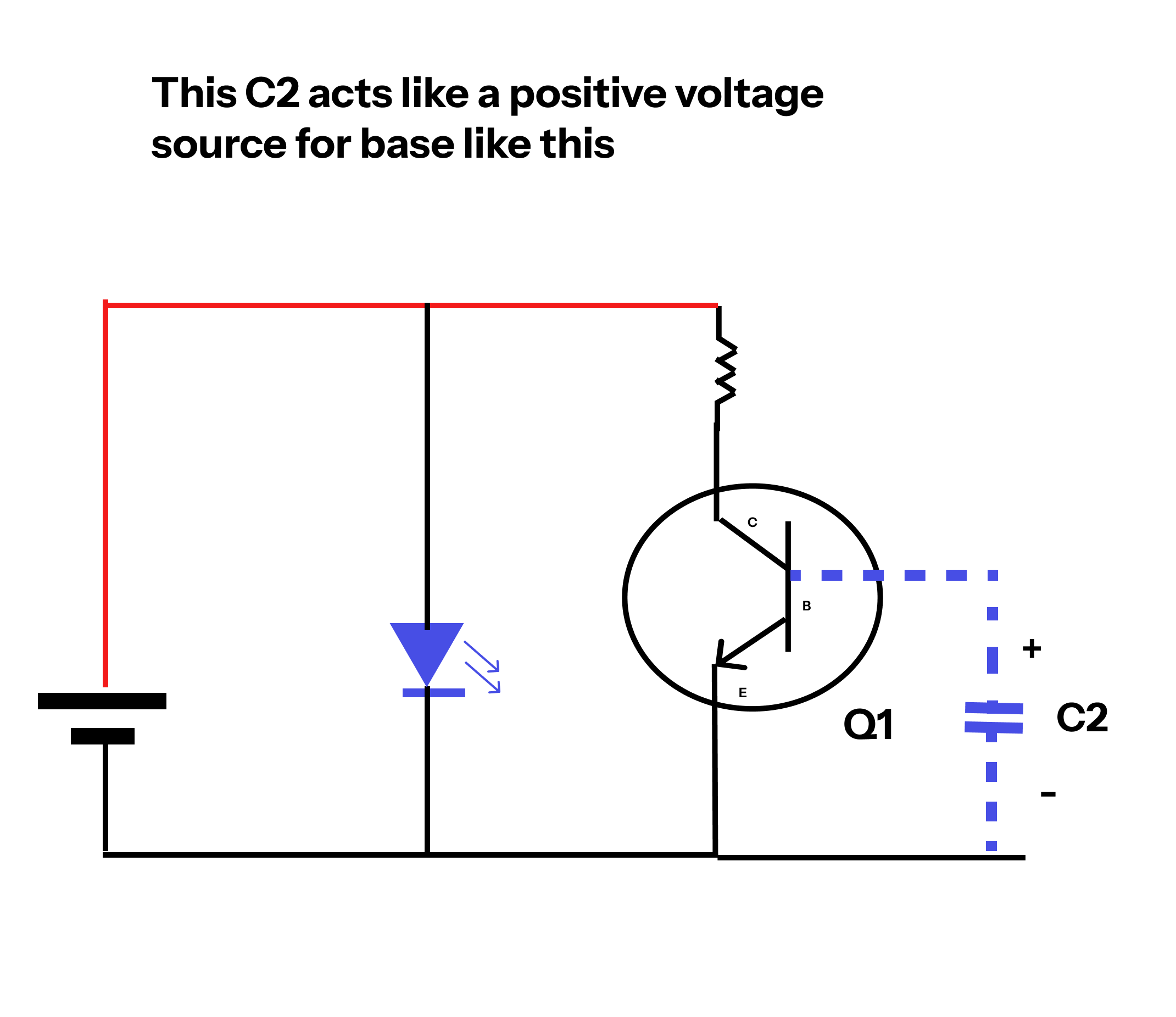
Looking at the polarity, the capacitor creates a reverse bias at the base of Q1, which causes Q1 to turn off.
I will provide a precise image to illustrate what this means, for better understanding.

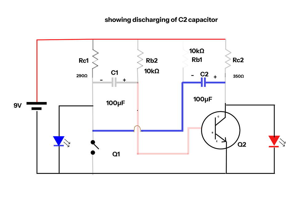
On the other hand, C1 is discharging, which creates a positive bias at the base of Q2. This forward bias causes Q2 to turn on.

I will provide a precise image to illustrate what this means, for better understanding.
That marks the end of the first cycle. In the next half, the same process occurs in reverse, with the roles of Q1 and Q2 switching.I’ll provide step-by-step images to illustrate each stage clearly.
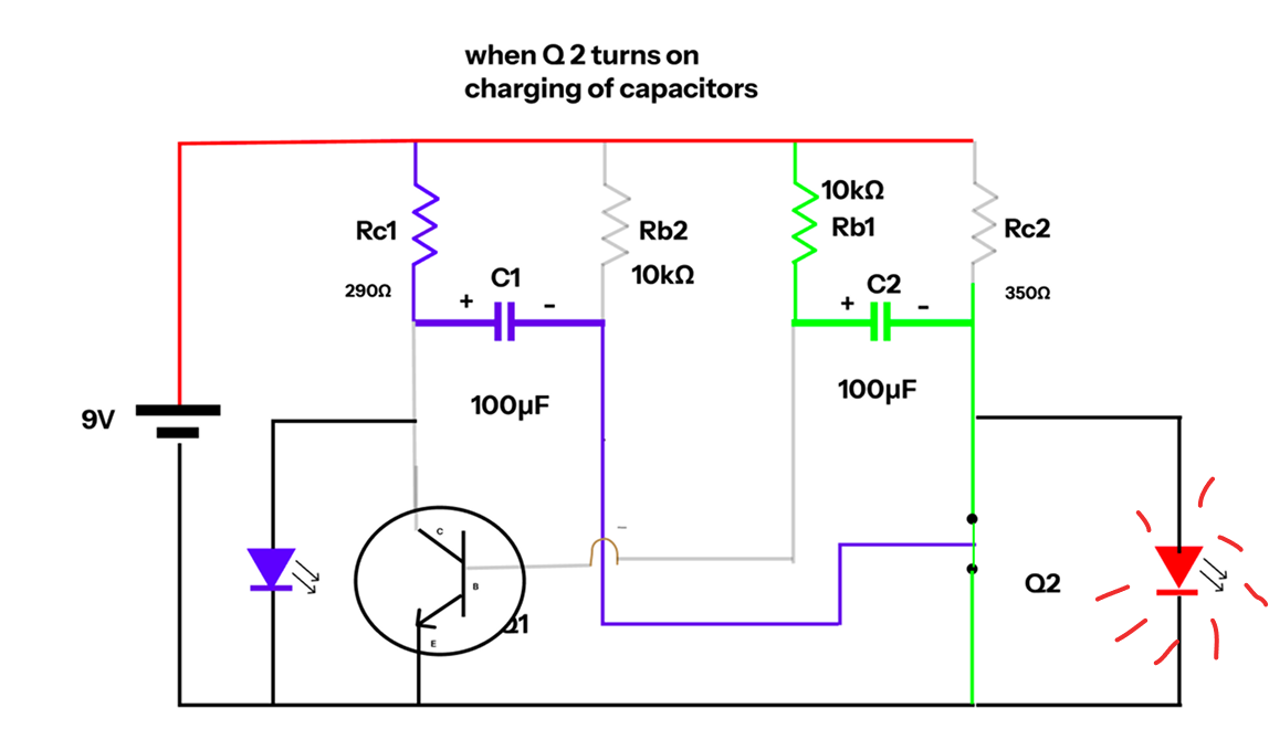
Step 2 (Q2 Turns On)
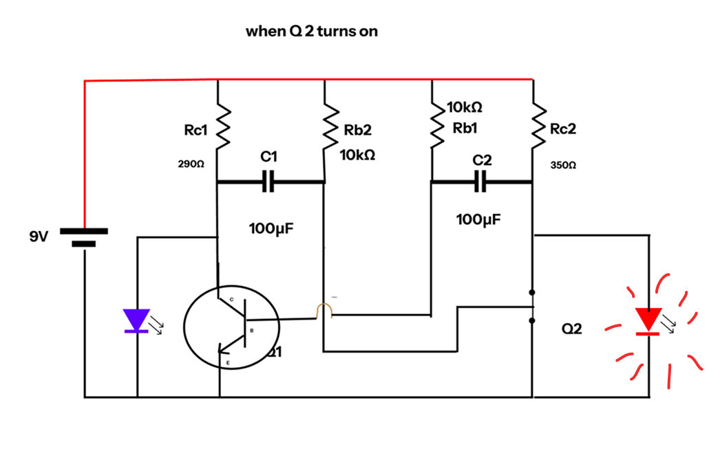

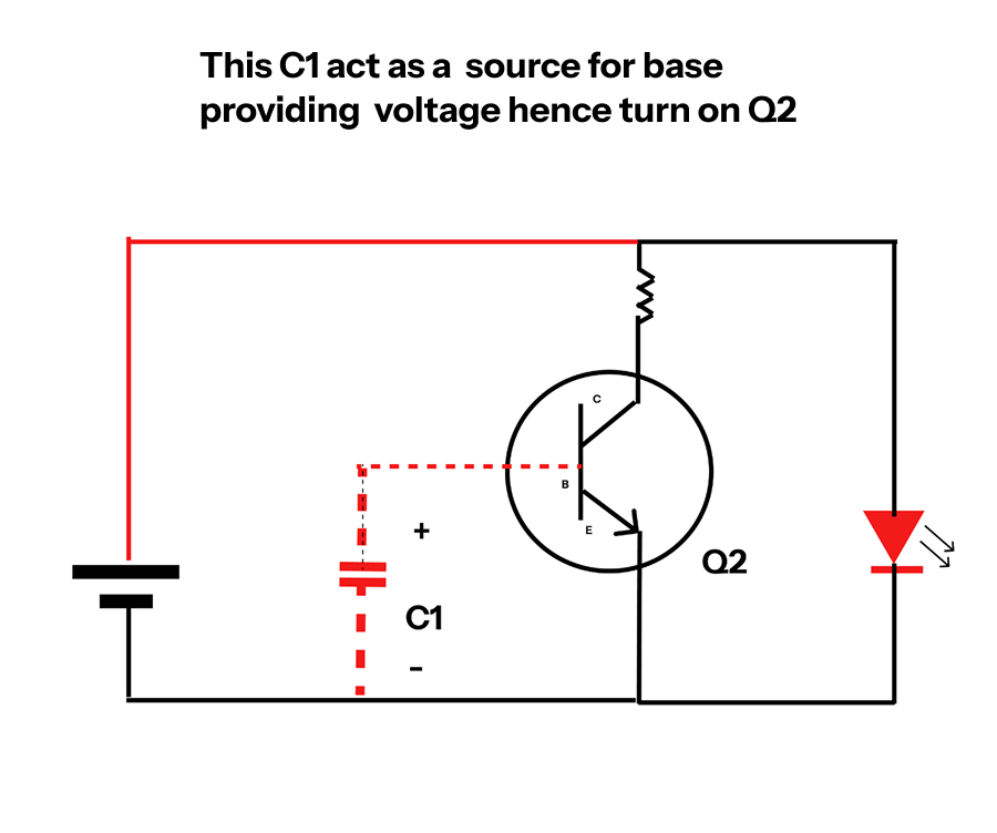
This C1 act as a reverse Biase for base of Q2 hence it will Turn off

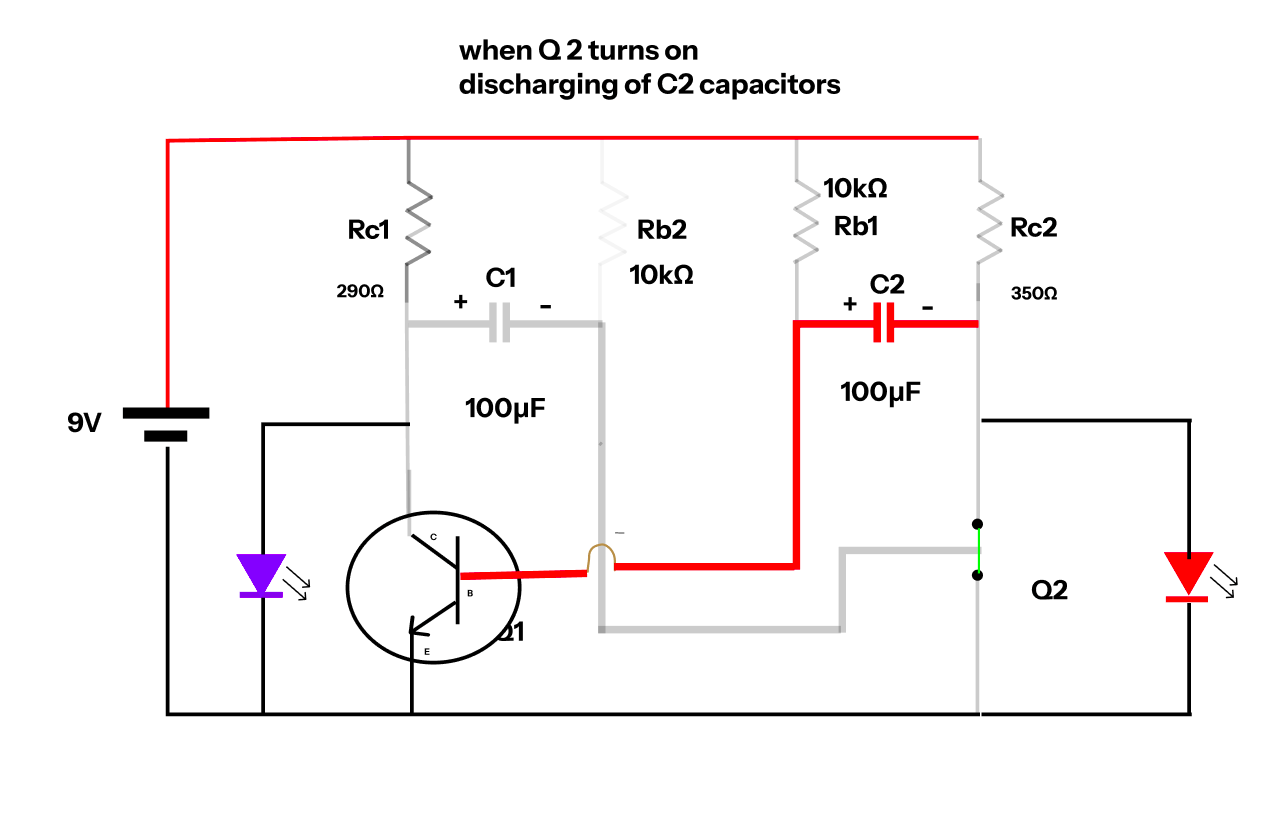
This lead to turn on Q1
The output wave form of Two transitor are given below
